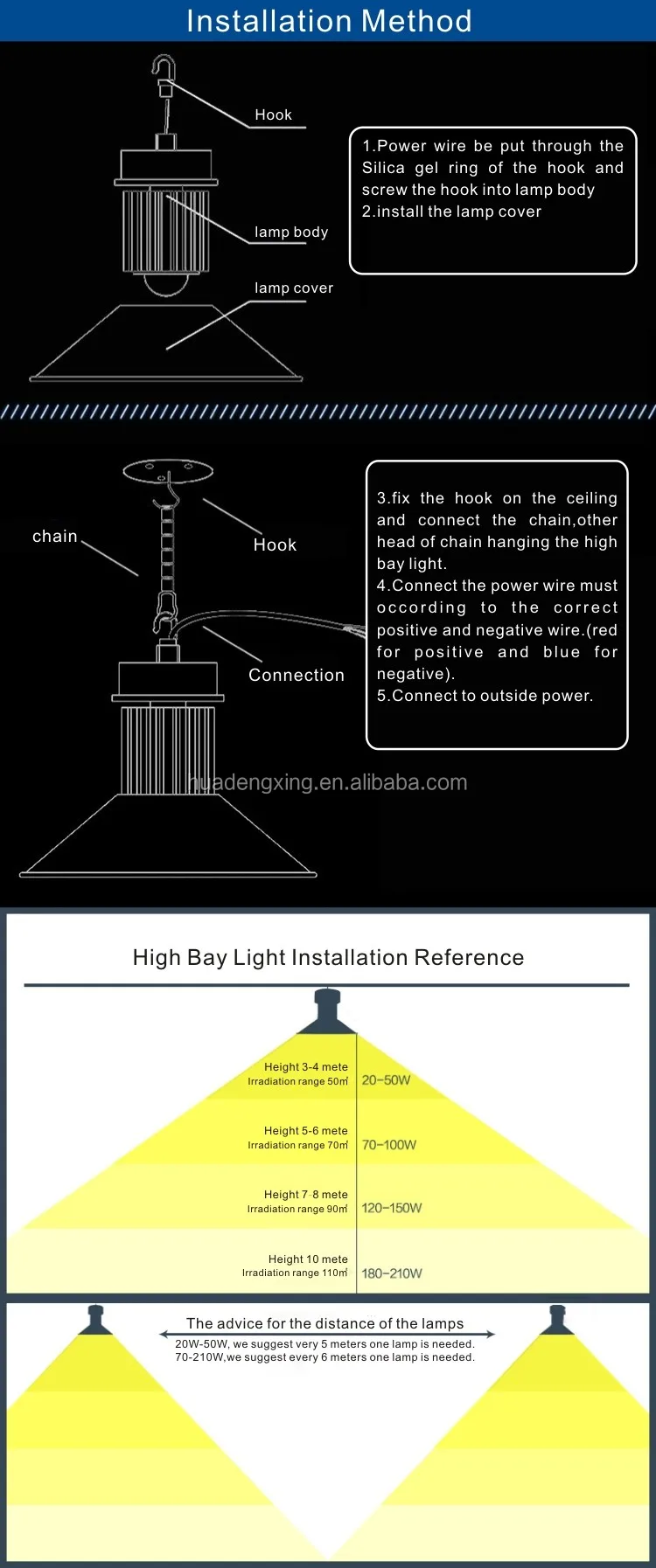
Eco linear high bay installation instructions. Hampton bay ceiling fan wiring schematic collections of wiring diagram for light and fan print replacing a ceiling fan pull.
Sammy april 27 2018 0930.

You can find out more Diagram below
Wiring diagram for high bay light. In accordance with dialight terms and conditions of sale and. How to connect dimmer for ufo led high bay lighting. My shop right now has four t8 fixtures with 2 bulbs each 8 foot long bulbs.
This light source is not intended as an emergency exit fixture or light. Ceiling fan wiring diagram australia best replacing a ceiling fan. Upgrading lighting who knows wiring and t5 high bay lights.
Hampton bay fan wiring schematic sample. 177 broad street 12th floor. Dimming terminal block connections led driver compartment removed cover 0 10v dimming.
Industrial high bay led luminaires installation maintenance information save these instructions for future reference if 1673 ul1598 pending cul pending suitable for operation in ambient not exceeding 40c dry locations only application wiring 1. Vigilant led high bay luminaire for industrial areas wiring diagram all statements technical information and recommendations contained herein are based on information and tests that dialight believes to be reliable. Pull field wiring into mounting bracket.
Its dim as hell. Connect supply wires to luminaire wire. I want to upgrade to six t5 high output fixtures with 6 bulbs each to brighten it up a lot.
If you have a direct electric current dimmer you can use the vaux12v port. Quorum ceiling fan wiring diagram circuit diagram symbols. The accuracy or completeness thereof is not guaranteed.
If you dont have a direct electric current dimmer you need not to use vaux12v. Whether it be used for dimming led high bay lights or to operate dimmable led parking lot lights 0 10v dimmers are a cost effective lighting control system that greatly help to reduce the cost you spend on unnecessarily expensive lighting. Step 1 disconnect power.
We need to connect the dim to the on your dimmer and connect the dim to the on your dimmer.


0 comments:
Post a Comment